When needed surge tanks can provide a critical feature to the hydraulic design of hydropower projects. The theoretical treatment of oscillation in a surge tank is difficult because of the.
Surge Tanks
We offer complete kits designed for single or dual use of Bosch 040 Walbro GSS341 GST450 and Deatschwerks DW200 DW301 and the new DW400 with extreme performance.
. Surge tank or surge chamber is a device introduced within a hydropower water conveyance system having a rather long pressure conduit to absorb the excess pressure rise in case of a sudden valve closure. Force during operation for linked systems with or without Surge Tanks. All surge tanks open to the atmosphere must be designed.
Water Hammer and Surge Tanks Cive 401 Mahanna Loeb Magalhaes 11192014 fWater Hammer Water Hammer is a pressure surge or wave that occurs when there is a sudden momentum change of a fluid the motion of a fluid is abruptly forced to stop or change direction within an enclosed space Water Hammer. The necessity of surge tank is judged whether length of pressure tunnel exceeds 500m or not. One of the important parameters in the design of surge tanks is the maximum and minimum water level within the tank.
Main outputs of the basic design are. Azhary Moghaddam 2004 proposed a general solution for optimizing the maximum. This document describes design formulas and design example of restricted orifice surge tank.
It is crucial to harmoniously Blend wonderful clothing with shoes Adhere to. To calculate the pressure rise of a Nitrogen Gas Spring and Surge Tank system first calculate the internal volume of the gas springs where V GS. The design and effect of hydraulic throttling of the surge tanks at Tonstad Hydropower Plant.
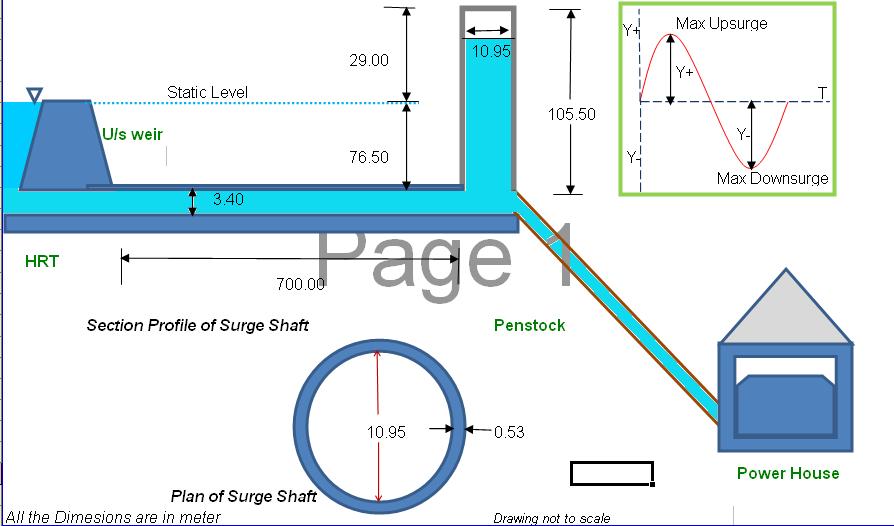
This type can ffely attenuate amplitude of the water level in the tank and has comparatively simple design. Principally they can mitigate the overpressure effects of. The height of surge tank is designed by the highest possible water level during the operation.
This is closely related to Kaspar Vereides work and his knowledge in the field of hydraulic transients and numerical computation has been invaluable for completion of the thesis. Two-Compartment designs typically are not used on applications that required 247 operations year round since the system would need to be shut down for maintenance. Surge tank details.
Intermediate liquid storage tanks surge tanks are commonly installed between processing areas of the plant. 3- 2013 2- Orifice surge tank. Here Surge Tanks or Stand Pipes are used to reduce the pressure surges.
Surge tanks are installed on large pipelines to relieve excess pressure caused by water hammer and to provide a supply of water to reduce negative pressure if a valve is suddenly opened. Choosing a Surge Tank and Determining Pressure Rise Solving for Pressure Rise when Nitrogen Gas Springs and Surge Tank is known. Inlet pipe 3inch NB.
Of flat-bottomed cylindrical above-ground storage tanks and under-ground storage tanks respectively. To absorb abnormal pressure increase in the tunnel by water hammering when load rejection or input power rejection. To absorb the abnormal pressure decrease in the tunnel by supplying water when rapid increase of discharge.
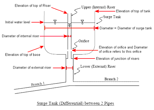
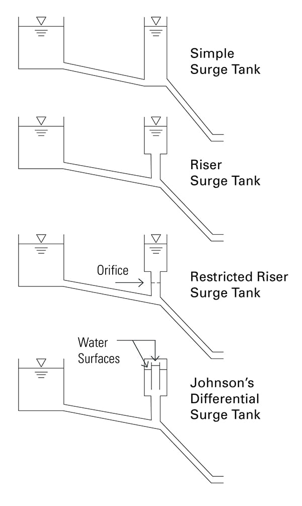
These days Restricted Ori ce Surge Tanks are usually adopted. A typical surge tank is shown in figure 6 as it would be used with a hydroelectric power plant. If the entrance to the surge tank is restricted by means of an orifice it is called an orifice tank.
This article deals primarily with surge chambers in hydroelectric power plants but brief reference is also made to surges in pipelines see Appendix 1. In general a long pressure tunnel the headrace tailrace of pumped storage power plant needs a surge tank. There are two main advantages in using a closed surge tank compared to the open type.
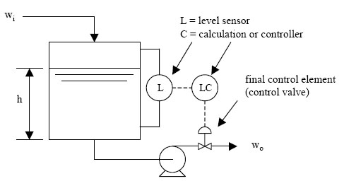
In a hydroelectric power plant or in a pumping station in order to avoid sudden large increase of pressure due to instantaneous valve closure sometimes a surge tank can be installed. Design example of surge tank. These pumps must pump through the modulating level-controller on the deaerator.
The surge tank is located between the almost horizontal or slightly inclined conduit and steeply sloping penstock and is designed as a chamber excavated. In this design the surge tank is located far from the turbine so that the elevation of the surge tank matches the elevation of the reservoir. Examples of design procedure for each type of tanks in chapters 4 through 8 are included in appendices.
For example lets suppose the pumps ran on-off from a level-controller in the tank like a condensate pump. When the flow to the turbine is reduced water flows into the surge tank and conversely for increased load the initial extra water required is from the surge tank. 85 show traditional design with open surge tanks the lower From 1975 on shows the typical layout for a hydropower plant with a closed surge tank.
We have chosen to design our Fuel Surge Tank kits to work with some of the most common used fuel pumps on the market fuel pumps that we know work satisfactory and are of good quality. The design in the Study is carried out at more detailed level than conducted in a feasibility study on a hydropower project in accordance with SW for the Study. To ensure that the image being not just modern but additionally classy.
The looks of the woman is her organization card in many conditions of existence. The valve might represent turbine gates which may open or close. A surge tank has following functions.
A simple surge tank is a vertical standpipe connected to a pipeline. Introduction Function of surge tank. Figure 934-6 Surge Tank Vertical and Cross Section9-28 Figure 934-7 Water Level in the Surge Tank at.
Surge tank some of the transient pressure is transmitted to the low-pressure system. Failure to operate the pumps continuously negates the purpose of the modulating valve. In addition in the case that a surge tank is constructed deep under the ground such as a tailrace surge tank the diameter of vertical shaft can be reduced by adding upper.
In addition a surge tank must have continuously running pumps. The three upper examples in Fig. Surge tanks are categorized in following 4 types.
The size of the tank should be such that water will not overflow when the turbine is suddenly shut down nor. Inlet pipe location from the bottom of the tank 1248 mm client want this at 1100 mm if possible attach the total process design calculations involved in surge tank. The surge tank can be an integral part of the deaerator commonly referred to as a Two-Compartment design or be a separate freestanding tank typically referred to as a Two-Tank design.
ــــــــــــــــــــــــــــــــــــSurge Tank Design Considerations for Controlling Water. 12 otations The following notations are applicable as common notations through the chapters in. - 150 - University Bulletin ISSUE No15 Vol.
Results of this study indicated that for the surge tank design with D 6 m and d 34 m head pressure fluctuations reached minimum level.

Pdf Design Of Surge Tank For Water Supply Systems Using The Impulse Response Method With The Ga Algorithm

Conceptual Design Of Storage Tanks Download Scientific Diagram
6 1 Surge Tank Model Engineering Libretexts
Hydraulic Design Of Surge Shaft Definition And Design Of Surge Shafts
Hydraulic Stability Of Surge Tanks

Today 39 S Extreme Diy Example Is A Home Scale Water Water Processing Plant Designed And Prototyped By Bob Cr Water Treatment Plant Water Treatment Aquaponics

Pdf Surge Tank Design Considerations For Controlling Water Hammer Effects At Hydro Electric Power Plants

Design Of Surge Tank Shaft Water Hammer Effect Hydropower Engineering Ioe Tu Pu Youtube
0 comments
Post a Comment